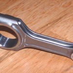
Minimum weight, maximum yield, the connecting rod is an emblematic forging part. Enduring some of the highest stresses in an engine, every step in the manufacturing process is determining to successfully produce reliable and performing rods. The choice of the material as well as the heat treatment must be carefully selected to reach the mechanical properties required by the engine manufacturer. Here are the main steps for manufacturing a connecting rod:
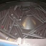
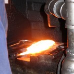
- The connecting rods are formed from 4340 alloy steel bars. Cut into lengths, they are conveyed to an induction heater and in seconds their temperature escalates to around 1250°C.
- Once it has reached a malleable condition, the billet is successively hammered in 3 impressions carved in a die block, progressively forming the rod.
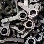
- Then comes the flashing operation, when the ledge of excess steel is removed, followed by the piercing of the centre.
- Final operation before starting the machining, the rods are placed in a cooling conveyor to reach the required mechanical properties. For a 4340 alloy, the hardness must range from 26HRC to 30HRC
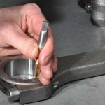
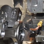
- The first machining operations are the face milling of perpendicular surfaces at the opposite ends of the rod, as well as the boring of the small end, to set fixed locators for further operations.
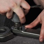
- Throughout the process, the rod undergoes different operations such as deburring, blending, polishing and shot blasting.
- Then comes several machining operations done on a CNC machining centre:
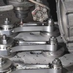
- machining of the outer profiles of the con rod caps
- boring of the bolt holes
- parting of the beam from the cap
- end milling, drilling, boring and chamfering of the caps
- rough cutting of the bore on the beam end
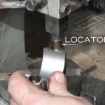
- The locators are pressed home on the 2 parts, after what the beams and the caps are fastened together.
- Both parts are then dotted, to confirm the correct alignment of the 2 parts.
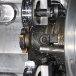
- After assembly, the outside profile of the beam is machined with a ball nose end mill.
- Finally the distance between the 2 ends is set by machining the big end.
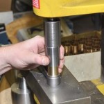
- The small end, mounted on the piston pin housing, is press-fitted with a aluminium nickel bronze alloy bushing with a 10T press.
For high end rods, the accuracy reaches +/- 0.0001-inch, centre to centre.